Removal and Installation
- Ultima Oil Pump Harley
- Ultima Oil Pump Manuals
- Ultima Evo Oil Pump Instructions
- Ultima Carburetor Manual
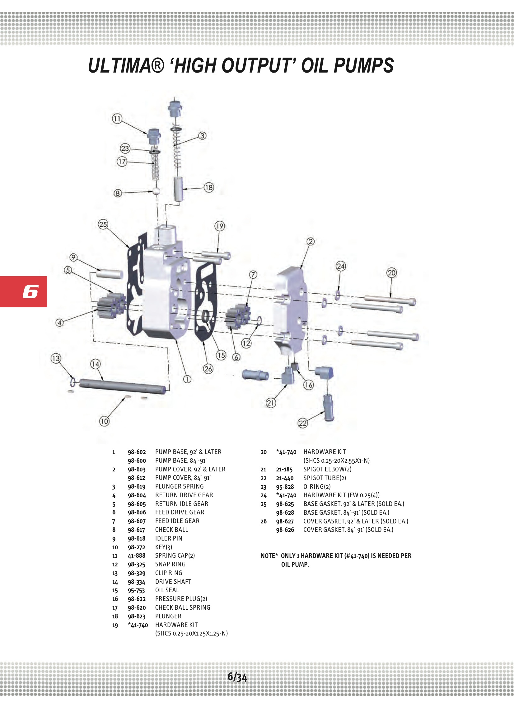
- Ultima Oil Pump Diagram
REMOVAL
The Ultima X Sampling Module - DC Pump Model described in this manual must be installed, operated, and maintained in strict accordance with the labels, cautions, warnings, instructions, and within the limitations stated. An Ultima X Sampling Module - DC Pump Model is designed to sample gases or vapors in air. It cannot sample the. Ultima pumps are checked on a Coordinate Measuring Machine, and flow tested on a test stand to insure the oil pumps are consistent from one pump to the next, and the motor is getting adequate oil. Pump performs with similar characteristics of the stock pump for volume and pressure. Ultima® shall have no obligation in the event an Ultima® part becomes defective in whole or in part as a result of improper installation, improper maintenance, improper use, abnormal operation, or any other misuse or mistreatment of the Ultima® part. Manual pumps are used for siphoning or transferring petroleum based fluids, detergents, antifreeze, chemicals, and more. List View Grid (59 items in Manual Pumps) 12 per page 12 per page 24 per page 48 per page. Click on Selected Product Manual to Download PDF Instructions Page. ENGINE PARTS REFFERENCE GUIDE Engine Parts Big Book Ultima Products Catalog call your Midwest Motorcycle Supply Sales Rep. Ultima® Products is distributed exclusively by Midwest Motorcycle Supply.
1. Remove the timing chain. Refer to EM-163, 'Removal'.
2. Remove oil pump assembly.
INSTALLATION
Installation is in the reverse order of removal.
Disassembly and Assembly
1. Oil pump housing
2. Outer rotor
3. Inner rotor
4. Oil pump cover
5. O-ring
6. Regulator valve set
7. Regulator valve


8. Spring
9. Regulator plug

10. Oil strainer
CAUTION: Before assembly apply new engine oil to the parts as shown above.
DISASSEMBLY
1. Remove the oil pump cover.
2. Remove inner rotor and outer rotor from oil pump housing.
3. Remove oil strainer from oil pump housing.
4. After removing regulator plug, remove spring and regulator valve.
INSPECTION AFTER DISASSEMBLY
Clearance of Oil Pump Parts
• Measure clearance with feeler gauge.
• Clearance between outer rotor and oil pump body (position 1).
Standard : 0.114 - 0.260 mm (0.0045 - 0.0102 in)
• Tip clearance between inner rotor and outer rotor (position 2).
Standard : Below 0.180 mm (0.0071 in)

• Measure clearance with feeler gauge and straightedge.
• Side clearance between inner rotor and oil pump body (position 3).
Standard : 0.030 - 0.070 mm (0.0012 - 0.0028 in)
• Side clearance between outer rotor and oil pump body (position 4).
Standard : 0.050 - 0.110 mm (0.0020 - 0.0043 in)
• Calculate the clearance between inner rotor and oil pump body as follows.
1. Measure the outer diameter of protruded portion of inner rotor (position A).
2. Measure the inner diameter of oil pump body with inside micrometer (position B).

(clearance 5) = (inner diameter of oil pump body B) – (outer diameter of inner rotor A)
Standard : 0.045 - 0.091 mm (0.0018 - 0.0036 in)
Regulator Valve
1. Visually inspect components for wear and damage.
Ultima Oil Pump Harley
2. Check oil pressure regulator valve sliding surface and valve spring.
Ultima Oil Pump Manuals
3. Coat regulator valve with engine oil. Check that it falls smoothly into the valve hole by its own weight.
If damaged, replace regulator valve set or oil pump body.
Regulator Valve Clearance
(Clearance 6) = D (Valve hole diameter) – E (Outer diameter of valve)
Standard : 0.040 - 0.097 mm (0.0016 - 0.0038 in)
If it exceeds the standard, replace the oil pump body.
CAUTION: Coat regulator valve with engine oil.
Check that it falls smoothly into the valve hole by its own weight.
Ultima Evo Oil Pump Instructions
Assembly
Ultima Carburetor Manual
Assembly is in the reverse order of disassembly.
• Assemble the inner rotor and outer rotor with the punched marks on the oil pump cover side.
CAUTION: Before assembly apply new engine oil to the parts as specified.
Oil cooler
Removal and Installation 1. Oil filter 2. Oil cooler bolt 3. Water pipe 4. Water hose 5. Oil cooler 6. O-ring 7. Oil pan 8. Water pipe 9. Relief valve 10. Water drain plug 11. Copper gask ...Other materials:
P1726 electric throttle control system
Description Electric throttle control actuator consists of throttle control motor, accelerator pedal position sensor, throttle position sensor etc. The actuator sends a signal to the ECM, and ECM sends the signal to TCM with CAN communication. DTC Logic DTC DETECTION LOGIC DTC CONFIRMAT ...
Ultima Oil Pump Diagram
P2118 throttle control motor
Description The throttle control motor is operated by the ECM and it opens and closes the throttle valve. The current opening angle of the throttle valve is detected by the throttle position sensor and it provides feedback to the ECM to control the throttle control motor to make the thrott ...
Corrosion protection
Description To provide improved corrosion prevention, the following anti-corrosive measures have been implemented in NISSAN production plants. When repairing or replacing body panels, it is necessary to use the same anti-corrosive measures. Anti-Corrosive Precoated Steel (Galvannealed Steel) ...